

Installing a Cattery Ventilation System
by R. Theron Cammer.
Originally published in The Cat Fanciers’ Almanac, March 1999
One of the biggest problems encountered by any cat breeder is the odor problem. I have walked into some breeders’ homes and nearly gagged at the smell! What an image such a breeder presents to the world! It is not easy to deal with multiple-cat odors, but it is possible. The first step, of course, is to keep everything scrupulously clean. Any whole cat, male or female, can urinate in inappropriate places. I hate cleaning, but I do it because it has to be done, and no ventilation system can replace adequate cleaning.
My wife and I have received many comments from people entering our home who say that if they had not seen our cats, they would not have known that we had any. Enough people have made the comment that I have certainly started believing them, where at first I had wondered if it could be so.
The first step we take, besides cleaning much more than we care to, is that there are litter boxes strategically placed all over the house. We have about twelve in use at all times, on all levels (two-story house with basement). We also use a lot of X-O® brand deodorizer – about ten squirts in each box each time it’s cleaned, and sometimes in between cleanings. Also, it really helps that my wife has a much more sensitive nose than I do and can tell that there’s an odor when I cannot (she says I don’t smell good). Also, whole cats that urinate in inappropriate places are not allowed outside of the cattery. I also suggest the use of scoopable litter. My wife and I only “scoop” thoroughly every other day. We find that if you wait until the third day, the clumps of urine start to fall apart, and the box retains odors too much. If you scoop more often, so much the better.
This article deals with the “do-it-yourself” installation of a cattery ventilation system, something that has helped us and our friends tremendously.
I have now installed four systems of varying complexity. Everyone for whom I have done so uses it daily and finds it extremely helpful in keeping odors down, especially with spraying males. It is also not expensive if you do the job yourself, and does not take long to install. My biggest problem is finding the time to do it.
We first installed one in our own cattery because, when my wife and I got married and I moved into her house, I built a cattery in the basement for the ten cats that I brought into the marriage (she had only four). What we found (especially when we painted it) is that we had a ventilation “dead space.” The fumes from cat odors and paint would linger for several days. This was unacceptable to my new bride’s nose, as well as to mine, so I decided to put in a ventilation system.
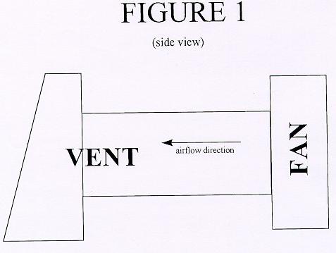
Step one in installing a system is to decide where it needs to be installed. It may be a complicated or a very simple system. Figures 1-3 show some of the ones I have done. (Click any image to enlarge)
To begin:
- Find where in your cattery the greatest concentration of odors is coming from. If it comes from everywhere, you’ve got a real problem! Decide where the worst place is.
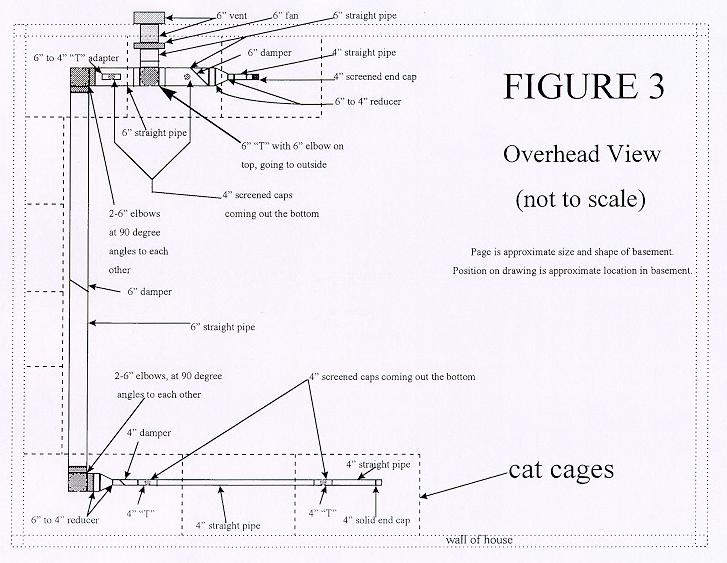
- Check the air flow in your house. The worst odors are probably where there is little, if any, flow of air. You can check this very easily by using anything that forms smoke; a cigarette is probably the easiest tool for this. Release smoke into the air and see what direction it takes. It probably does not go toward the cattery, and may very well have the least movement where the odors are produced (spraying males, etc.). This is where you need to put your intake for the exhaust system. You can install more than one intake, as was done in figure 3.
- Next, from the outside of the building, figure out where you would like the exhaust to exit. If you want it to exhaust out the back, but the cattery is in the front, it can still be done. It will just require more pipe to be run.
- Figure out the best way to get from where the intake needs to be to where you want it to exhaust. The best way includes as few bends in the pipe as possible, and the shortest distance. More bends, multiple inlets and longer runs mean that you’ll need a bigger fan.
- Figure out the diameter of pipe you need. If you are only moving a small amount of air a short distance, 4″ dryer vent pipe is fine. If you have multiple inlets, long distances or large volumes of air to move, consider using 6″ pipe similar to dryer vent pipe. You may need to use both sizes.
- Consider the noise the fans generate. A 55 cfm fan creates little noise and cannot usually be heard, but can definitely be heard when the house is all quiet. On the other hand, a 240 cfm fan creates more noise, which can definitely be heard. I highly suggest not putting a larger size fan under your bedroom. You will almost certainly find it too loud to run at night.
Step two is to assemble the materials you’ll need to install the system. Things you will need to consider buying are:
- Vent. Either 6″ diameter or 4″ diameter. Make sure that it has a screen and/or flap so that insects, rodents and cold air don’t come in when the fan is shut off.
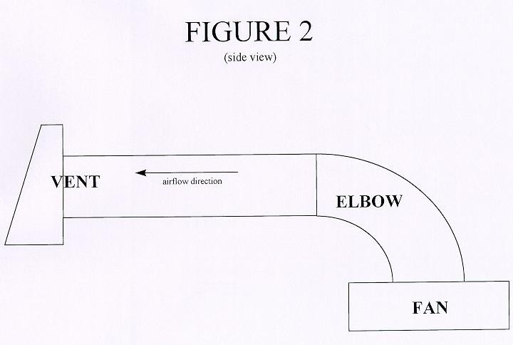
- Straight pipe. Find out how many linear feet of pipe you need, and of what size. For example, if you are only going through a wall (as in figure 1), all you need is a 4″ diameter connector to make your adapter from and the vent itself. If your situation is similar to figure 2, you will need the vent, 4′ of 4″ pipe, and a 4″ connector. The system shown in figure 3, a more complicated system, used 42′ of 6″ pipe and 10′ of 4″ pipe.
- Elbows. Figure out how many elbows will be needed to make the turns necessary. In figure 1, no elbows are needed. In figure 2, one 4″ elbow is needed. In figure 3, three 6″ elbows are needed. Figure 4 is a detail drawing of the fan area of figure 3.
- Dampers. A damper is a flat plate with a handle on it. The large flat part goes in the pipe and the handle sticks out. You adjust the air flow of the whole system by changing how much air the damper allows through that part of the pipe. Figure 3 used three dampers, two 6″ ones and one 4″ one.
- Solid end caps. Use these whenever you have an end to the pipe that you don’t want air to go through. Figure 3 used one 4″ end cap. It was installed this way to allow for future expansion along the same wall.
- Screened end caps. If you’re lucky, you may be able to buy these. If not, you’ll have to make these yourself. I’ll show you how to do so later. Figure 3 used four 4″ ones. If you have to make them yourself, you’ll need some expanded wire mesh to put over the ends. I used the wire mesh used to keep leaves out of the gutters on a house.
- “T”s. If you split off in more than one direction, you’ll need a T. Figure 3 uses one 6” T, shown in detail in figure 4.
- Adapter. This you’ll have to make yourself. If your fan is at the end of the pipe, you’ll only need one. If it’s installed in the pipe, you’ll need two. Use connectors for this purpose. Figures 1and 2 used one 4″ adapter each, while figure 3 used two 6″ adapters. An adapter is shown in photo 1.
- Connectors. These are used to connect two sections of pipe the same size. You’ll need one to connect any pipe or elbows to the vent, one or two for making into adapters and anyplace else where one pipe connecting to another pipe cannot slide into the other pipe. Figures 1and 2 each used one connector (one end went to the vent and the other end was made into an adapter), while figure 3 used two 6″ connectors for the fan and four 4″ connectors in various places. These are not shown in the drawings.
- Reducers. These are used when going from one size pipe to another. Figures 1and 2 didn’t use any. Figure 3 used two reducers going from 6″ down to 4″. * “T” Reducer. Figure 3 used one T reducer that was 4″, cut into the side of a 6″ pipe. Since a 6″ to 4″ T reducer could not be found, a 4″ T was changed to fit the 6″ pipe.
- Axial fan. The fans I used are Dayton(r) brand axial fans. These are designed to be in the middle of the airstream (middle of the pipe). Figures 1and 2 used 55 cfm (cubic feet per minute) fans, 411/16″ square, while figure 3 used a 240 cfm 6″ diameter, since it was designed to ventilate the cattery area of an open basement in a ranch-style house, a much larger area. This particular brand of fans ranges from 30 cfm to 110 cfm for the 411/16″ size and from 240 cfm in the 6″ size up to 560 cfm for the 10″ size. Other brands will have different ratings. For comparison, a stove exhaust hood exhausts about 160 cfm. These fans are not expensive, so buy a good one. The one in my home was installed four years ago and has run almost continuously since then. With the Dayton(r) brand fans you will also need a separate cord set. You must have this as the fan has a unique connection, and it costs less than $2.00. An axial fan is shown in photo 2. * Duct tape. You will need a 2″ wide roll, and it will actually be used for what it was created for, putting on duct work (pipe).
- Screws. Various sizes will be used. I use drywall screws of various lengths for practically everything.
- Bolts or machine screws. You will need four or six of them to attach the fan to the adapter(s), along with nuts, lock washers and twice as many flat washers as you have screws.
- Metal strapping. This is used to hold up the pipe, and consists of a metal strap with periodic holes punched in it.
- Electrical junction box. This will be needed to hook up the fan’s cord to the power supply.
- Junction box cover. To seal up the junction box after the wires are connected.
- Electrical power cable. Two-wire, solid-wire cable is fine, and it doesn’t have to be of a heavy gauge. 14 gauge is certainly adequate. Three-wire cable is not necessary, as the fan has no grounding connection.
- Electrical switch. You will sometimes want to turn off power to the fan, even if it’s only when you need to replace it or clean it.
- Electrical switch box. You’ll need a box to put the switch in.
- Switch plate. The plastic or metal plate put over the switch box.
- Wire nuts. Used to connect the cord set to the power supply from the switch and, depending on how your power source is set up, you may need to use them going from your current wiring into the switch.
- Electrical tape. Usually needed for something.
- Wire staples. Used to staple up your new electric power supply cord that goes to the cord set.
- Wood. You will need small pieces of wood to brace the fan. Nothing larger than a 1″ x 2″ will be needed.
- “Pop” rivets. These may be needed to fasten items together.
- Caulking. Used for caulking around the vent on the outside of the house.

While you may find that there are additional minor items you will need, those listed will certainly be the most-needed items. Now, let’s put this thing in. First, we want to put together anything we can at our workbench, because it is much easier, for example, to make an adapter at the workbench than it is to make it in between floor joists in the overhead.
So, let us make the adapter(s) first. The adapter(s) can be made from straight pipe, reducers, Ts or connectors. Take and cut into the end of your adapter with tin snips far enough to create “ears” or “petals” that can be spread out far enough to cover the outside edges of the fan (see photo 1). Use a pencil to mark the fan’s holes onto the adapter(s), then drill your holes in the ears. I suggest you drill the holes 1/64″ larger than the diameter of the bolts or machine screws to allow for easy assembly. You may also have to slightly enlarge the holes in the fan itself to accommodate the screws.
When all the adapters are done, bolt them to the fan. Use a flat washer under the head of the bolt or machine screw and another flat washer and a lock washer under the nut on the other side. Tighten so that the lock washer becomes flat and there are no gaps in the lock washers. Do not over-tighten or you may strip the threads or break something. Do not use “pop” rivets for this task, as they may loosen up over time and cannot readily be tightened. Now your fan is attached to one or two adapters and is ready to be put in (see photo 3).
If you have to make screened end caps, let us do that now. Get out however many connectors you need and your gutter screen. Cut circles out of the gutter screen with tin snips about 2″ larger in diameter than your end cap. You can then either put them over the end of the end cap and fold the 1″ lip (on either side) down over the cap and “pop” rivet it on, or you can find something a bit smaller than the inside of the end cap and fold the lip down and then put it inside the end cap and rivet it in place. If you put it on the outside you may want to put either a pipe clamp over the edges of the screen or some duct tape to ensure that the cats don’t injure themselves on a sharp edge. Now, these are ready to go, and that’s about all you can do at your workbench.
The next step, then, is to carefully measure where you want the hole to go through the wall. If you can, choose a place where you can drill through wood. You can drill through concrete or brick, but it’s much harder. You may very likely have to drill through your siding, too. Drill a pilot hole first with a 1/4″ extra length drill bit. You use a 1/4″ bit because the pilot hole for the hole saw arbor is most likely 1/4″. Then check the other side to make sure it came out where you wanted it to. If you make an error in where it was placed, it’s much easier to fill a 1/4″ hole back in than it is a 41/4″ or 6″ hole. If you need to drill through concrete or brick you will have to drill through that with a masonry bit or else drill through the mortar between the bricks, realizing that it will dull a normal bit severely.
If your hole is indeed where you want it, then you will need to drill the full-size hole with a “hole saw” and, if going through brick or concrete, saw and chisel a hole in the masonry. For use with 4″ pipe, your hole saw will need to be 41/8″ or 41/4″ diameter. For use with 6″ pipe, you probably will not be able to find a hole saw larger than 6″ diameter, so plan on having to use a keyhole saw or a jigsaw to enlarge the hole. You will almost certainly also need a 12″ hole saw “arbor extension” to get that far back into the house.
If going through concrete or brick, you will need to use a pencil to draw a square on the outside of the masonry large enough to put your vent pipe through (4 1/4″ or 6 1/4″). Then take a masonry blade on a circular saw and saw along the lines. Bear in mind the brick or concrete probably will not be cut all the way through, and certainly it won’t be at the corners. That’s where you’ll use a large cold chisel and hammer to chisel out the masonry. The sawing is only to make neat edges on the outside of the hole. The outside edge should, however, end up being covered up by the square part of the vent that sticks outside. One thing you can do to cut down drastically on how much chiseling you have to do is to take a masonry bit and drill holes that almost touch each other along the inside of the saw line. The masonry will then be much easier to chisel out.
When you’re through the masonry (or if you don’t have to go through masonry) use your hole saw to cut the full-size hole all the way through the wall.
Next, install the vent. Insert the vent through the hole from the outside of the house, then fasten it with screws to the siding. Then caulk the seam. If you have masonry, you can probably just caulk the seam, but do it as your very last step to ensure that the vent doesn’t move and mess up the caulking.
Then go into the house and install either a connector and piping or the fan’s adapter (depending on how far away from the vent the fan needs to be) into the vent pipe. Duct tape the joint when assembled.
Next we brace the fan. Run wood strips between floor joists so that the fan can be bolted or screwed to the strips for support (see photo 6 for a 6″ fan installation). You may need to take the fan off the adapters to put this all in. You can choose to either run the bolts or machine screws through the adapters, fan and wood, or else find another way to fasten the fan to the wood strips. Make sure that you leave the electrical connection where you can get to it when it comes time to hook it up.
If you have any run of pipe further than about 4′, use metal strapping to support the pipe. If you don’t have to run the pipe any further, you’re done with everything but the electrical work. If not, assemble the rest of the piping, including any dampers you will need. If you have any screened end caps that hang down toward the floor, I suggest that you “pop” rivet those on before putting on the duct tape. Use duct tape on all joints so that you don’t have air leakage and to hold the joints together. Here’s a tip: if you have long (over 2′) pieces of pipe that keep popping apart at the lengthwise seams as you’re putting them up, put a piece of duct tape over the seam to keep it from popping apart. You may very well have to cut some pipe to the proper length with tin snips. You can either put those pieces together with a connector or you can buy a tool to allow you to put the crimps in the end of the pipe to reduce the diameter so as to allow it’s insertion into another section.
It is now time to put the electrical work in. If you do not know what you are doing with electrical work, STOP HERE, and hire an electrician.
I suggest that you work backwards so that the very last thing that you do is to connect the power.
First, put in the electrical junction box, close enough to the fan so that the cord set will reach from the fan into the junction box. Hook up the cord set and insert it into the junction box. Secure it with staples.
Then, put up your switch box wherever you want the switch to be. Run the electrical cable from the junction box to the switch box and connect the wires inside the junction box. Install junction box cover. Staple the power cable in place from the junction box to the switch box, supporting it every foot or so. CAUTION: Your local builder’s codes may require certain techniques (such as putting the cable in conduit, for example) to do this or else require a licensed electrician to do the electrical work.
The next step is to hook up the wire you just ran to the switch. Then, run your power cable to your power source, whether it’s an existing electrical outlet or switch, or whatever. You may need to install another junction box.
EXTREMELY IMPORTANT: Next, shut off the electrical power to your power supply by tripping the circuit breaker or pulling the fuse before you attempt to hook it up! Use an electrical tester to verify that there is no power on in your source.
Hook up the power source and then install all cover plates not already installed. Ensure that your new electrical switch is turned off.
Turn the power back on and test the fan. Adjust any dampers as needed to get the best ventilation flow. Allow one hour for the air flow to become established. You may need to install vents between your cattery and other rooms to allow warm air to come into the cattery, so the cattery doesn’t become too cold.
The last thing that you should do is test your furnace to ensure that you haven’t created a lack-of-draft problem with your furnace. Do this test twice: once now, and once on one of the coldest days of the year. You do the test like this: turn on all exhaust fans in the house (stove exhaust hoods, bathroom fans, the cattery exhaust fan you just installed and any other exhausts) at the same time. Go to the furnace and, with your cigarette, ensure that there is draft up the furnace exhaust, and that exhaust is not being sucked back down into the house. It is unlikely that this could happen, except with a very large exhaust fan, but it is much better to be sure. If you have any questions regarding how a fireplace will affect draft, consult your heating contractor.
Congratulations! You should now be very pleased with the reduction in odors. If not, you need to investigate other solutions, such as doing away with carpeting that the cats have soiled, painting raw wood so that urine doesn’t seep into it, and just plain keeping the cattery clean. If everything is Formica’ and vinyl, it will be very easy to clean.
If you are using one of the smaller fans, I doubt if you will notice much difference in your heating or air conditioning bill. We have noticed no difference at all in ours. This set-up makes it so that the source of the strongest odors is the last place in the house that the air is before it goes right outdoors.
The simple set-ups in figures 1and 2 cost less than $100 each, even with buying the hole saw and hole saw arbor extension. The more complicated one shown in figure 3 cost about $250. These figures do not include any cost for labor, as I did all the work myself, including the electrical work. You may be able to save quite a bit of money if you can borrow or rent any tools you don’t already have. I had most all of them on hand already. Here’s a list of tools you will likely need:
- 1/2″ drill motor for hole saw (do not use a smaller one. It won’t take it.)
- 1/4″ or 3/8″ drill motor for smaller holes
- 41/8″ or 4 1/4″ or 6″ hole saw blade with arbor
- 12″ hole saw arbor extension
- extension cord
- flashlight or other light
- keyhole or jig saw to enlarge hole if necessary
- pocket knife for tape
- common hand tools (screwdrivers, wrenches, pliers, etc.)
- caulking gun
- wiring pliers
- electrical tester
- drill bits for smaller holes, including for “pop” rivets
- center punch to make a dimple to start drilling * tin snips
If going through masonry:
- circular saw
- masonry blade for circular saw (More than one may be required. They wear very fast.)
- heavy hammer (3 lb. suggested)
- large cold chisel (3/4″ wide suggested)
- masonry bits
